Ray,Simple Camera and Object
Utils:Ray Class

由此,获得了射线方程\(P=A+tb\),其每个参数的含义如下:
- \(P\):3D空间中该射线上的一点
- \(A\):射线的起点
- \(b\):表示射线方向的单位向量
- \(t\):从射线起点\(A\)到点\(P\)的直线长度
其中只有\(t\)是一个实数,其余参数都是3D空间中的向量。由此可以创建一个Ray类:
ray.h
| //
// Created by Klingsor on 2026/5/29.
//
#ifndef RT1WEEK_RAY_H
#define RT1WEEK_RAY_H
class ray {
public:
//构造函数
ray(){}
ray(const vec3& origin, const vec3& direction):orig(origin), dir(direction){}
//返回方向和光线的起点,const的目的是让它们为只读。
//此方法类似于get
const vec3& origin() const {return orig;}
const vec3& direction() const {return dir;}
//射线方程P=A+tb
//const是为了让const实例也能调用该方法,而不是仅允许const实例调用该方法
[[nodiscard]] point3 at(float t) const {
return orig+t*dir;
}
private:
point3 orig;
vec3 dir;
};
#endif //RT1WEEK_RAY_H
|
现在可以传入光线的起点和方向构建ray的实例。
Sending Rays Into the Scene

根据光线追踪的原理,所涉及的步骤如下:
1. 计算”眼睛“(视点/相机)穿过像素的光线
2. 确定光线和哪些物体相交
3. 计算最近光线的颜色
这些步骤都发生在3d空间中,因此需要创建一个3d场景,并构造相应的相机和视口。
相机是眼睛,也是光线的起点。在这里,将相机坐标设为(0,0,0),即位于原点。
视口是位于3d空间的矩形,类似相机的取景框。在单个像素的宽高相同时,视口的宽高比(aspect ratio)应和输出图像保持一致。
从相机指向视口中心的向量正交于视口,这个向量的模长叫焦距,规定其值为\(1.0\)。
由此,可以定义坐标系:将相机的坐标设为\((0,0,0)\),y轴指向正上方,x轴指向右侧,-z轴指向观察方向。(这是右手坐标系)

这时就出现了冲突:抛开z轴来看,原点位于视口的中心,但输出图像以图像的左上角为原点,并且y轴和坐标系的y轴相反。在第一节中,程序通过ppm图像输出渲染结果,在写入数据时按照了从左到右、从上到下的顺序,即便不使用ppm,通常也需要按照类似的顺序进行数据写入。
因此需要得到视口的左上顶点在3d空间中的坐标;为了逐像素写入,还需要得到向下一个像素移动时,空间坐标的变化量,它们会替代原本在第一节中写死的输出图像宽高。以下代码假定使用的宽高比为\(16:9\)、输出图像宽度为\(400px\)、视口高度为\(2\)。
main.cpp main()函数
| //Image
auto aspect_ratio=16.0/9.0;
int image_width=400;
int image_height=image_width/aspect_ratio<1?1:image_width/aspect_ratio;
//Camera
auto focal_length=1.0; //焦距
auto view_height=2.0; //视口高度
auto view_width=view_height*((double)image_width/image_height); //视口宽度
auto camera_center=point3(0,0,0); //相机/视点坐标
//从视口左边缘到右边缘、上边缘到下边缘的向量
auto view_u=vec3(view_width,0,0);
auto view_v=vec3(0,-view_height,0);
//像素在水平和垂直方向上的步进增量
//这表示每向右/下移动一个像素,在3d空间中需要移动的距离
//3d空间是指视口所在的3d空间。我们将焦距设为1,这里的步进增量也是相对这个单位1定义的坐标系
auto pixel_delta_u=view_u/image_width;
auto pixel_delta_v=view_v/image_height;
//获得视口左上角顶点在3d空间中的坐标
auto view_upper_left=camera_center-vec3(0,0,focal_length)-view_v/2-view_u/2;
//获得视口左上角顶点像素的像素中心
auto pixel00_loc=view_upper_left+0.5*(pixel_delta_u+pixel_delta_v);
|
场景的构造完成后,需要确定每个像素的颜色。
定义方法ray_color(),传入从视点指向当前像素的光线,得到当前像素的颜色,这是前文提到的光线追踪的第2、3步。此处将方法体简化为默认返回黑色(\(rgb(0,0,0)\)),则修改后完整的main.cpp如下:
main.cpp
| #include <iostream>
#include <fstream>
#include "utils/utils.h"
color ray_color(const ray& r) {
return color(0,0,0);
}
int main() {
//输出流对象
//使用fstram替代cout标准输出,以避免异常的不可见字符
std::ofstream out("image.ppm", std::ios::out | std::ios::binary);
if (!out) {
std::cerr << R"(创建文件失败)" << std::endl;
return 1;
}
    //Image
    auto aspect_ratio=16.0/9.0;
    int image_width=400;
    int image_height=image_width/aspect_ratio<1?1:image_width/aspect_ratio;

    //Camera
    auto focal_length=1.0;     //焦距
    auto view_height=2.0;      //视口高度
    auto view_width=view_height*((double)image_width/image_height);  //视口宽度
    auto camera_center=point3(0,0,0);    //相机/视点坐标

    //从视口左边缘到右边缘、上边缘到下边缘的向量
    auto view_u=vec3(view_width,0,0);
    auto view_v=vec3(0,-view_height,0);

    //像素在水平和垂直方向上的步进增量
    //这表示每向右/下移动一个像素,在3d空间中需要移动的距离
    //3d空间是指视口所在的3d空间。我们将焦距设为1,这里的步进增量也是相对这个单位1定义的坐标系
    auto pixel_delta_u=view_u/image_width;
    auto pixel_delta_v=view_v/image_height;

    //获得视口左上角顶点在3d空间中的坐标
    auto view_upper_left=camera_center-vec3(0,0,focal_length)-view_v/2-view_u/2;
    //获得视口左上角顶点像素的像素中心
    auto pixel00_loc=view_upper_left+0.5*(pixel_delta_u+pixel_delta_v);
//Render && PPMInput
out<<"P3\n"<<image_width<<' '<<image_height<<'\n'<<"255\n";
for (int j=0;j<image_height;j++) {
//输出进度,\r表示光标回到当前行行首
std::clog<<"\r当前进度:"<<(image_height-j)<<' '<<std::flush;
for (int i=0;i<image_width;i++) {
//计算当前像素中心,光线会从视点指向当前像素中心
auto pixel_center=pixel00_loc+i*pixel_delta_u+j*pixel_delta_v;
//计算指向当前像素的光线的方向
auto ray_direction=pixel_center-camera_center;
//声明当前光线的实例
ray r(camera_center,ray_direction);
//使用pixel_color方法得到当前像素的颜色
auto pixel_color=ray_color(r);
//将颜色输出到文件
write_color(out,pixel_color);
}
}
std::clog<<"\r结束 \n";
out.close();
return 0;
}
|
运行程序,应该输出一张尺寸为400*225PX的黑色图像。
在此基础上可以实现简单的渐变:修改方法ray_color(),根据当前像素的y轴坐标决定白色和蓝色的混合率,输出从上到下由蓝色向白色渐变的图像:
方法ray_color()
| color ray_color(const ray& r) {
//将光线转换为单位向量
vec3 unit_direction=unit_vector(r.direction());
//将y坐标的范围从[-1,1]映射到[0,1],便于之后按比例混合颜色
//由于主函数规定的视口高度为2,以视口中心为0,则高度的范围就是【-1,1】
auto a=0.5*(unit_direction.y+1.0);
//返回白色和蓝色混合后的颜色
return (1.0-a)*color(1.0,1.0,1.0)+a*color(0.5,0.7,1.0);
}
|
Adding a Sphere
在构建场景和摄像机后,需要向场景中添加物体,球体是在三维空间中求解最简单的形状。在编写代码前,首先需要了解如何判断光线和球体相交:
\[x^2+y^2+z^2=r^2\]
上述方程代表中心位于原点、半径为\(r\)的球体的表面。给定一个三维空间中的点\((x,y,z)\),按方程左侧的公式进行计算得到结果p,则如果\(p>r^2\),该点位于球体外侧,即它在一个半径更大的球体的表面上;若\(p<r^2\),则该点位于球体的内部,即它在一个半径更小的球体的表面上;若\(p=r^2\),则该点位于球体表面。
这一方程可以推广到圆心位于\((C_x,C_y,C_z)\)的球体上,推广后判断点\((x,y,z)\)是否在球体上的方程为:
\[(C_x-x)^2+(C_y-y)^2+(C_z-z)^2=r^2\]
用\(P(t)\)表示需要检查和球体的点\((x,y,z)\),表示需要检查的这个点在指定射线上。注意到,向量\(C-P(t)\)与自身的点乘可表示为:
\[(C-P(t)) \cdot (C-P(t))=(C_x-x)^2+(C_y-y)^2+(C_z-z)^2\]
带入方程可得:
\[(C-P(t)) \cdot (C-P(t))=r^2\]
接下来,将射线方程带入上述方程:
\[(C-(Q+td)) \cdot (C-(Q+td))=r^2\]
为了判断点是否在在该圆上,使用逆推的方法:假定该点在圆上,则方程成立,此时t是方程中唯一的未知值,可以根据\(t\)是否有解判断这一假设是否成立,进而判断该点是否在圆上:
由于向量的点乘遵循线性乘法的交换律、结合律和完全平方公式,可以将上式展开为:
\[\begin{gather} (-td +(C-Q)) \cdot (-td+(C-Q))=r^2 \\ t^2d \cdot d-2td\cdot(C-Q)+(C-Q)\cdot(C-Q)=r^2 \\ t^2d \cdot d-2td\cdot(C-Q)+(C-Q)\cdot(C-Q)-r^2=0 \end{gather}\]
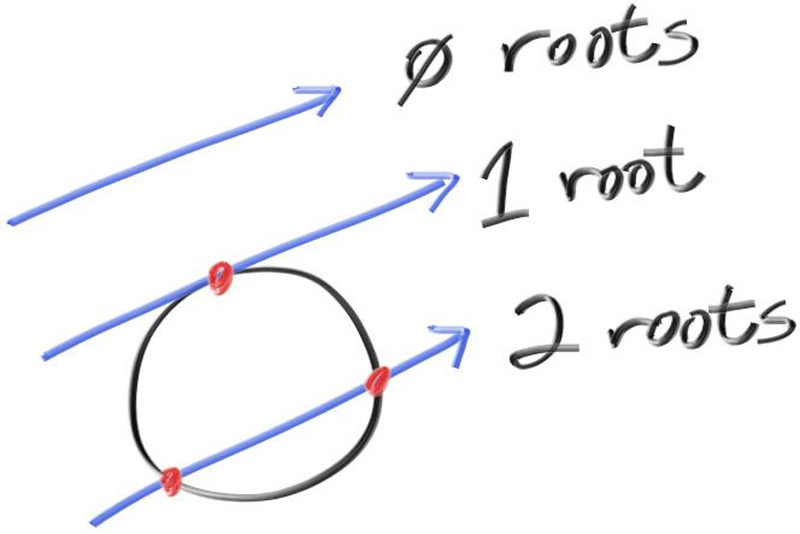
根据二次方程的判别式\(\sqrt{b^2-4ac}\)可以判断方程的根的数量。从上述方程中可以提取出判别式中的参数:
\[\begin{gather} a=d \cdot d \\ b=-2d \cdot (C-Q) \\ c=(C-Q) \cdot (C-Q)-r^2 \end{gather}\]
基于以下理论,可以在先前的代码基础上绘制sphere,在main.cpp中修改ray_color方法和新增hit_sphere方法:
ray_color方法和hit_sphere方法
| /**
*
* @param center 球体中心
* @param radius 球半径
* @param r 光线
* @return 是否在球上/内部
*/
bool hit_sphere(const point3& center,double radius,const ray& r) {
auto delta_a=dot(r.direction(),r.direction());
auto delta_b=-2*dot(r.direction(),(center-r.origin()));
auto delta_c=dot(center-r.origin(),r.direction())-radius*radius;
return sqrt(delta_b*delta_b-4*delta_a*delta_c)>=0;
}
color ray_color(const ray& r) {
//如果当前点在球上/内部,则返回红色,否则返回渐变背景颜色
if (hit_sphere(point3(0,0,-1),0.5,r))return color(1.0,0.0,0.0);
//将光线转换为单位向量
vec3 unit_direction=unit_vector(r.direction());
//将y坐标的范围从[-1,1]映射到[0,1],便于之后按比例混合颜色
//由于主函数规定的视口高度为2,以视口中心为0,则高度的范围就是【-1,1】
auto a=0.5*(unit_direction.y+1.0);
//返回白色和蓝色混合后的颜色
return (1.0-a)*color(1.0,1.0,1.0)+a*color(0.5,0.7,1.0);
}
|
运行程序,应该输出一张位于图像中心、直径是1/2图像高度的图片。
Shading with Surface Normals
定义表面法线为指定坐标处和物体表面垂直的单位向量,且表面法线总是指向物体向外的一侧。对于球体,表面法线的计算公式是\(P-C\),其中\(P\)是位于球体表面上的一点,\(C\)是该球体的中心。
法线贴图是将物体的表面法线值映射到颜色范围内生成的图像。对于上一节中绘制的球体,可以修改ray_color方法和hit_sphere方法绘制它的法线贴图:
ray_color方法和hit_sphere方法
| /**
* @param center 球体中心
* @param radius 球半径
* @param r 光线
* @return 射线方程 P(t)=A+td 中的t,即光线从起点经过了多长的路径到达了指定像素
*/
double hit_sphere(const point3& center,double radius,const ray& r) {
auto delta_a=dot(r.direction(),r.direction());
auto delta_b=-2.0*dot(r.direction(),(center-r.origin()));
auto delta_c=dot(center-r.origin(),r.direction())-radius*radius;
auto discriminant=delta_b*delta_b-4.0*delta_a*delta_c;
if (discriminant<0.0)return -1.0;
//射线和球面的交点可能存在一个或多个,但在绘制时近处的会遮挡远处的,因此此处返回值更小的根。
else return (-delta_b-std::sqrt(discriminant))/(2.0*delta_a);
}
color ray_color(const ray& r) {
//计算当前光线如果能与球面相交,则经过了多长的距离
auto t=hit_sphere(point3(0.0,0.0,-1),0.5,r);
if (t>0.0) {
//计算当前光线从起点经过t的距离和球面相交时,交点的坐标并归一化。
//由于计算法线是相对物体自身,所以需要减去球体的中心坐标,以模拟当前位于原点(局部坐标)
auto p=unit_vector(r.at(t)-point3(0.0,0.0,-1.0));
return 0.5*color(p.r+1.0,p.g+1.0,p.b+1.0);
}
//将光线转换为单位向量
vec3 unit_direction=unit_vector(r.direction());
//将y坐标的范围从[-1,1]映射到[0,1],便于之后按比例混合颜色
//由于主函数规定的视口高度为2,以视口中心为0,则高度的范围就是【-1,1】
auto a=0.5*(unit_direction.y+1.0);
//返回白色和蓝色混合后的颜色
return (1.0-a)*color(1.0,1.0,1.0)+a*color(0.5,0.7,1.0);
}
|
在上述判别式的基础上,考虑简化\(t\)的计算。观察求根公式:
\[x = \frac{-b \pm \sqrt{b^2 - 4ac}}{2a}\]
注意到分母包含因子\(2\),参数\(b\)也包含因子2,试使\(b=-2h\),则有求根公式的简化:
\[\begin{aligned}
& \frac{-b \pm \sqrt{b^2 - 4ac}}{2a} \\
= & \frac{-(-2h) \pm \sqrt{(-2h)^2 - 4ac}}{2a} \\
= & \frac{2h \pm 2\sqrt{h^2 - ac}}{2a} \\
= & \frac{h \pm \sqrt{h^2 - ac}}{a}
\end{aligned}\]
将\(b=-2h\)带入\(b=-2d \cdot (C-Q)\)中,得到\(h=d \cdot (C-Q)\),据此简化hit_sphere方法:
简化后的hit_sphere方法
| /**
* @param center 球体中心
* @param radius 球半径
* @param r 光线
* @return 射线方程 P(t)=A+td 中的t,即光线从起点经过了多长的路径到达了指定像素
*/
double hit_sphere(const point3& center,double radius,const ray& r) {
auto oc=center-r.origin();
auto delta_a=dot(r.direction(),r.direction());
auto h=dot(r.direction(),oc);
auto delta_c=dot(oc,oc)-radius*radius;
auto discriminant=h*h-delta_a*delta_c;
if (discriminant<0.0)return -1.0;
else return (h-std::sqrt(discriminant))/(delta_a);
}
|
Abstraction Class:Hittable
Note
hitable,可击中对象,不止指3D空间中实体物体的表面,也包括云、雾、或类似这样存在体积的东西。
为了解决存在多个物体的情况,可以将物体抽象为hittable类。对于所有可击中对象,都至少应该包含一个hit方法。
hit()方法用于判断指定光线能否在\([t_{min},t_{max}]\)范围内被击中,返回布尔值,并通过输出参数返回一个碰撞切片对象。
class hittable
| //所有可击中对象的父类
class hittable {
public:
//使用默认的析构函数
virtual ~hittable() = default;
virtual bool hit(const ray& r, double t_min, double t_max, hit_record& rec) const = 0;
};
|
其中,hit_record是输出参数,存储了特定碰撞的信息,包括碰撞点、碰撞点和光线起点的距离以及碰撞点的法线信息。如果发生了碰撞,hit方法会直接修改它的值。
class hit_record
| //单次碰撞的切片数据
class hit_record {
public:
//碰撞交点在世界空间下的坐标
point3 position;
//碰撞交点和光线起点的距离
double t;
//法线向量
vec3 normal;
};
|
现在考虑一个问题:对于透明或部分透明的材质,光从内部射出和从外部射入的效果存在显著差异。例如,光从空气射入水中和从水中射入空气中的折射率不同。为了在计算时能区分二者,需要在碰撞切片类hit_record中增加了两个成员:
front_face:布尔值,记录光线是否从外部来set_face_normal():接收光线来源和可击中对象被击中点的向外法线,根据点积计算光线来源是内部还是外部并记录。
hit_record
| //单次碰撞的切片数据
class hit_record {
public:
//碰撞交点在世界空间下的坐标
point3 position;
//碰撞交点和光线起点的距离
double t;
//法线,与光源来源相反
vec3 normal;
//光线来源方向
bool front_face;
//计算光线来源方向和法线
void set_face_normal(const ray& r,const vec3& outware_normal) {
//如果碰撞点向外法线和光线方向相反(夹角大于90度),则点积小于0,记为true
front_face=dot(r.direction(),outware_normal)<0;
//如果碰撞点向外法线和光线方向相同,则法线需要反转,以保证法线始终和光线来源相反
normal=front_face?outware_normal:-outware_normal;
}
};
|
为此,具体的可击中对象类中的逻辑也要略作调整,取消直接设置法线,通过对应方法设置法线和光线来源方向,此处以实体类sphere为例。
hit方法
| //判断是否击中
//rec是输出参数
bool hit(const ray &r, double t_min, double t_max, hit_record &rec) const override {
auto oc=center-r.origin();
auto delta_a=dot(r.direction(),r.direction());
auto h=dot(r.direction(),oc);
auto delta_c=dot(oc,oc)-radius*radius;
//判断交点数量
auto discriminant=h*h-delta_a*delta_c;
if (discriminant<0)return false;
//检查交点是否在range t_min,t_max 内
auto root=(h-std::sqrt(discriminant))/delta_a;
if (root<t_min||root>t_max){
//检查较大根
root=(h+std::sqrt(discriminant))/delta_a;
if (root<t_min||root>t_max)return false;
}
//这里直接把数据写进函数参数的rec
rec.t=root;
rec.position=r.at(root);
rec.set_face_normal(r,(rec.position-center)/radius);
return true;
}
|
A List of Hittable Objects
我们需要一个容器,用于存储场景中的可击中对象,它应该是hittable的子类,以便后续加入包围盒逻辑时能够嵌套可击中对象列表。
在最简单的光线追踪器模型中,渲染器会遍历射向每个像素对应的3d坐标的射线,每一束射线都会调用一次可击中对象列表的hit方法,向下层层递推最终返回距离光源最近的碰撞状态切片。
hittable_list.h
| //
// Created by Klingsor on 2026/6/4.
//
#ifndef RT1WEEK_HITTABLE_LIST_H
#define RT1WEEK_HITTABLE_LIST_H
#include <memory>
#include <vector>
#include "hittable.h"
#include "../core/ray.h"
using std::make_shared;
using std::shared_ptr;
//可击中对象列表
//继承hittable是为了可以将列表也视为一个可击中对象,以便在需要时进行嵌套
class hittable_list : public hittable {
public:
//使用shared指针简化操作,实际项目不推荐
std::vector<shared_ptr<hittable>> objects;
//创建一个空的可击中列表在语义上是合理的,因此需要无参构造函数
hittable_list(){};
hittable_list(shared_ptr<hittable> object){ add(object); }
void add(shared_ptr<hittable> object){ objects.push_back(object); }
void clear(){objects.clear();}
bool hit(const ray& r, double t_min, double t_max, hit_record& rec) const override {
hit_record temp_record;
//当前最近的碰撞点和视点的距离
double closest_so_f=t_max;
//当前是否存在能够碰撞的点
bool isHit=false;
//遍历当前列表中的所有可击中对象,返回最近的碰撞切片
for (const auto& object : objects) {
if (object->hit(r,t_min,closest_so_f,temp_record)) {
isHit=true;
rec=temp_record;
closest_so_f=rec.t;
}
}
return isHit;
}
};
#endif //RT1WEEK_HITTABLE_LIST_H
|
现在,可以删除main.cpp中的it_sphere方法,转而应用前文中抽象出的类。
main.cpp
| #include <iostream>
#include <fstream>
#include "math/rtweek.h"
#include "shape/hittable_list.h"
#include "shape/sphere.h"
#include "shape/hittable.h"
color ray_color(const ray& r,const hittable_list& world) {
//检查当前射线是否和实体对象相交
hit_record temp_rec;
if (world.hit(r,0.001,infinity,temp_rec)) {
//返回交点的法线映射的颜色
return 0.5*(temp_rec.normal+color(1.0,1.0,1.0));
}
//如果没有交点,则绘制渐变背景
//将光线转换为单位向量
vec3 unit_direction=unit_vector(r.direction());
//将y坐标的范围从[-1,1]映射到[0,1],便于之后按比例混合颜色
//由于主函数规定的视口高度为2,以视口中心为0,则高度的范围就是【-1,1】
auto a=0.5*(unit_direction.y+1.0);
//返回白色和蓝色混合后的颜色
return (1.0-a)*color(1.0,1.0,1.0)+a*color(0.5,0.7,1.0);
}
int main() {
//输出流对象
//使用fstram替代cout标准输出,以避免异常的不可见字符
std::ofstream out("image.ppm", std::ios::out | std::ios::binary);
if (!out) {
std::cerr << R"(创建文件失败)" << std::endl;
return 1;
}
//Image
auto aspect_ratio=16.0/9.0;
int image_width=400;
int image_height=image_width/aspect_ratio<1?1:image_width/aspect_ratio;
//Camera
auto focal_length=1.0; //焦距
auto view_height=2.0; //视口高度
auto view_width=view_height*((double)image_width/image_height); //视口宽度
auto camera_center=point3(0,0,0); //相机/视点坐标
//从视口左边缘到右边缘、上边缘到下边缘的向量
auto view_u=vec3(view_width,0.0,0.0);
auto view_v=vec3(0.0,-view_height,0.0);
//像素在水平和垂直方向上的步进增量
//这表示每向右/下移动一个像素,在3d空间中需要移动的距离
//3d空间是指视口所在的3d空间。我们将焦距设为1,这里的步进增量也是相对这个单位1定义的坐标系
auto pixel_delta_u=view_u/image_width;
auto pixel_delta_v=view_v/image_height;
//获得视口左上角顶点在3d空间中的坐标
auto view_upper_left=camera_center-vec3(0,0,focal_length)-view_v/2-view_u/2;
//获得视口左上角顶点像素的像素中心
auto pixel00_loc=view_upper_left+0.5*(pixel_delta_u+pixel_delta_v);
//world
//创建可击中对象列表并添加两个shpere
hittable_list world;
world.add(make_shared<sphere>(point3(0.0,0.0,-1.0),0.5));
world.add(make_shared<sphere>(point3(0.0,-100.5,-1.0),100));
//Render && PPMInput
out<<"P3\n"<<image_width<<' '<<image_height<<'\n'<<"255\n";
for (int j=0;j<image_height;j++) {
//输出进度,\r表示光标回到当前行行首
std::clog<<"\r当前进度:"<<(image_height-j)<<' '<<std::flush;
for (int i=0;i<image_width;i++) {
//计算当前像素中心,光线会从视点指向当前像素中心
auto pixel_center=pixel00_loc+i*pixel_delta_u+j*pixel_delta_v;
//计算指向当前像素的光线的方向
auto ray_direction=pixel_center-camera_center;
//声明当前光线的实例
ray r(camera_center,ray_direction);
//使用ray_color方法得到当前像素的颜色
auto pixel_color=ray_color(r,world);
//将颜色输出到文件
write_color(out,pixel_color);
}
}
std::clog<<"\r结束 \n";
out.close();
return 0;
}
|
输出图像如下:

Utils:Interval Class
观察已有的代码可以发现,\(t_\text{min}\)和\(t_\text{max}\) 总是成对出现,考虑实现一个区间类以管理具有最大值和最小值的区间,并替代已有代码中的\(t_\text{min}\)和\(t_\text{max}\) 。
interval.h
| //
// Created by Klingsor on 2026/6/4.
//
#ifndef RT1WEEK_INTERVAL_H
#define RT1WEEK_INTERVAL_H
#include "rtweek.h"
class interval {
public:
double min;
double max;
//不带参数时构造一个空集
interval():min(+infinity),max(-infinity){}
interval(double min, double max):min(min),max(max){}
//区间长度
double size()const{return max-min;}
//判断区间是否包含某个值(闭区间)
bool contains(double x)const{return min<=x && x<=max;}
//判断区间是否包含某个值(开区间)
bool surrounds(double x)const{return min<x && x<max;}
static const interval empty,universe;
};
const interval interval::empty=interval(+infinity,-infinity);
const interval interval::universe=interval(-infinity,+infinity);
#endif //RT1WEEK_INTERVAL_H
|
Abstraction Class:Camera
和可击中对象一样,相机和场景的代码也可以被抽象为camera类,它负责以下工作:
将相关代码从main.cpp移动到类中,使用时实例化并设置输出图像的分辨率,再调用render方法。
camera
| //
// Created by Klingsor on 2026/6/5.
//
#ifndef RT1WEEK_CAMERA_H
#define RT1WEEK_CAMERA_H
#include "../shape/hittable.h"
#include "../shape/hittable_list.h"
#include "../shape/sphere.h"
#include "../math/rtweek.h"
class camera {
public:
//将输出图像宽度和宽高比作为成员变量,此处的初始值仅作为默认,实际渲染时可以在调用render方法前修改为实际值
double aspect_ratio=1.0;
int image_width=100;
//接收可击中对象列表,初始化世界空间和摄像机,逐像素发射光线计算渲染结果
void render(std::ostream& out ,const hittable& world) {
init();
//PPM文件头
out<<"P3\n"<<image_width<<' '<<image_height<<'\n'<<"255\n";
//逐像素渲染
for (int j=0;j<image_height;j++) {
//输出进度,\r表示光标回到当前行行首
std::clog<<"\r当前进度:"<<(image_height-j)<<' '<<std::flush;
for (int i=0;i<image_width;i++) {
//计算当前像素中心,光线会从视点指向当前像素中心
auto pixel_center=pixel00_loc+i*pixel_delta_u+j*pixel_delta_v;
//计算指向当前像素的光线的方向
auto ray_direction=pixel_center-camera_center;
//声明当前光线的实例
ray r(camera_center,ray_direction);
//使用ray_color方法得到当前像素的颜色
auto pixel_color=ray_color(r,world);
//将颜色输出到文件
write_color(out,pixel_color);
}
}
std::clog<<"\r结束 \n";
}
private:
int image_height=100;
point3 camera_center;
//像素在水平和垂直方向上的步进增量
point3 pixel_delta_u;
point3 pixel_delta_v;
//视口左上角顶点像素的像素中心
point3 pixel00_loc;
void init() {
image_height=image_width/aspect_ratio<1?1:image_width/aspect_ratio;
//Camera
auto focal_length=1.0; //焦距
auto view_height=2.0; //视口高度
auto view_width=view_height*((double)image_width/image_height); //视口宽度
camera_center=point3(0,0,0); //相机/视点坐标
//从视口左边缘到右边缘、上边缘到下边缘的向量
auto view_u=vec3(view_width,0.0,0.0);
auto view_v=vec3(0.0,-view_height,0.0);
//像素在水平和垂直方向上的步进增量
//这表示每向右/下移动一个像素,在3d空间中需要移动的距离
//3d空间是指视口所在的3d空间。我们将焦距设为1,这里的步进增量也是相对这个单位1定义的坐标系
pixel_delta_u=view_u/image_width;
pixel_delta_v=view_v/image_height;
//获得视口左上角顶点在3d空间中的坐标
auto view_upper_left=camera_center-vec3(0,0,focal_length)-view_v/2-view_u/2;
//获得视口左上角顶点像素的像素中心
pixel00_loc=view_upper_left+0.5*(pixel_delta_u+pixel_delta_v);
}
color ray_color(const ray& r,const hittable& world) {
//检查当前射线是否和实体对象相交
hit_record temp_rec;
if (world.hit(r,interval(0,infinity),temp_rec)) {
//返回交点的法线映射的颜色
return 0.5*(temp_rec.normal+color(1.0,1.0,1.0));
}
//如果没有交点,则绘制渐变背景
//将光线转换为单位向量
vec3 unit_direction=unit_vector(r.direction());
//将y坐标的范围从[-1,1]映射到[0,1],便于之后按比例混合颜色
//由于主函数规定的视口高度为2,以视口中心为0,则高度的范围就是【-1,1】
auto a=0.5*(unit_direction.y+1.0);
//返回白色和蓝色混合后的颜色
return (1.0-a)*color(1.0,1.0,1.0)+a*color(0.5,0.7,1.0);
}
};
#endif //RT1WEEK_CAMERA_H
|
在此基础上,main.cpp可以进行简化:
main.cpp
| #include <iostream>
#include <fstream>
#include "math/rtweek.h"
#include "core/camera.h"
#include "shape/hittable_list.h"
#include "shape/sphere.h"
#include "shape/hittable.h"
int main() {
//输出流对象
//使用fstram替代cout标准输出,以避免异常的不可见字符
std::ofstream out("image.ppm", std::ios::out | std::ios::binary);
if (!out) {
std::cerr << R"(创建文件失败)" << std::endl;
return 1;
}
//world
//创建可击中对象列表并添加两个shpere
hittable_list world;
world.add(make_shared<sphere>(point3(0.0,0.0,-1.0),0.5));
world.add(make_shared<sphere>(point3(0.0,-100.5,-1.0),100));
//camera
//创建相机和世界
camera cam;
cam.image_width=400;
cam.aspect_ratio=16.0/9.0;
//渲染
cam.render(out,world);
//关闭输出流
out.close();
return 0;
}
|